| 14 | Filling tanks with the help of pumps |
|
|
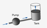
| Main | A cylindrical tank is filled with water through a pipe or hose at the bottom of that tank with the help of a pump. Data of the pressure of the water at the bottom of the tank is taken as a function of time. In a second experiment, the tank is discharged after having been filled with the pump. The same hose is used for discharging and for filling. More…
|
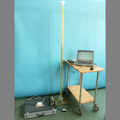
Photographs | |
| Movies |
|
| Data files | |
| Models | |
| |
| Sections | |
|
| |
| Description | DESCRIPTION OF EXPERIMENT |
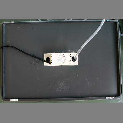
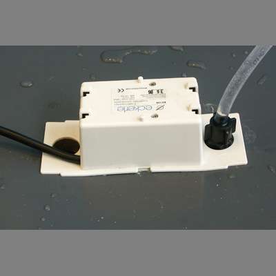
| Experiment | A cylindrical tank is filled with water through a pipe or hose at the bottom of the tank with the help of a pump. Water is taken from a wide shallow container having (approximately) the same level as the bottom of the tank. Data of the pressure of the water at the bottom of the tank is taken as a function of time. To reduce the volume of the tank, a cylindrical rod having a slightly smaller diameter is placed inside the tank. In a second experiment, the tank is discharged after having been filled with the pump (Data). The same hose is used for discharging and for filling. The hose is simply removed from the pump outlet, and the water is allowed to flow into a shallow container. The hose stays at the level of the bottom of the tank during both parts of the experiment. There is a little bit of water in the tank before charging it. |
| Dimensions | Tank: Inner radius: 20 mm, Radius of rod: 15 mm Hose: Length: 4.00 m, Inner diameter: 7.0 mm
|
| |
| Sections | |
|
| |
| Assignment | A POSSIBLE PATH THROUGH THE INVESTIGATION… |
| Basics | Investigate the experiment, make sure you understand the setup of the pump, pipe, and tank, together with the source of water. Plot the data to get a feeling for the dynamical process. Estimate time constants for filling and for discharging. Create a word model for the system and its processes. Create a formal dynamical model, import data, simulate the model and determine the parameters of the model by comparing simulation and experimental data.
|
Particulars | Try to separate the resistive effects of the pipe and the pump. Is it possible to parameterize the pressure loss in the pump?
|
| |
| Sections | |
|
| |
| Model | MODEL EQUATIONS AND MORE… |
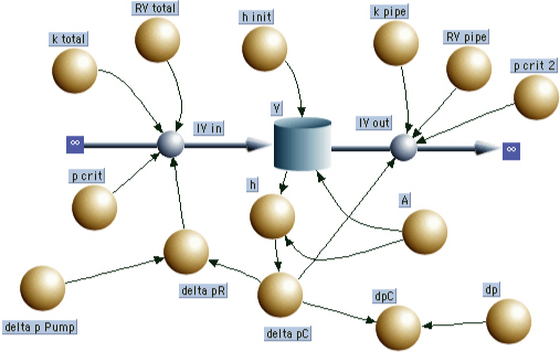
| | Laws of balance d/dt (V) = + IV_in - IV_out
INIT V = A*h_init
Flows IV_in = IF (TIME < 213) THEN IF (delta_pR > p_crit) THEN k_total*SQRT(delta_pR) ELSE delta_pR/RV_total ELSE 0
IV_out = IF (TIME > 213) THEN IF (delta_pC > p_crit_2) THEN k_pipe*SQRT(delta_pC) ELSE delta_pC/RV_pipe ELSE 0
Relations delta_pR = delta_p_Pump - delta_pC
delta_pC = 1000*9.81*h
h = V/A
dpC = delta_pC/1000+dp
Parameters h_init = 0.07
k_total = 1.6e-7
delta_p_Pump = 15800
k_pipe = 3e-7
dp = 100.8
A = PI*(0.02^2 - 0.015^2)
RV_total = 5.5e8
p_crit = 5000
RV_pipe = 1.6e8
p_crit_2 = 2000 |
| |
| Sections | |
|
| |
| Questions | SOME SIMPLE QUESTIONS… |
| 1 | When the tank is filled or discharged, water flows. Do you expect the flows to be laminar or turbulent? What aspect of your models is influenced by your answer to this question? |
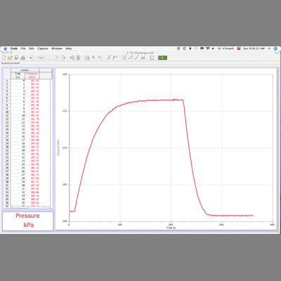
2 | Why does the tank only fill to a certain height? (See the graph of Data taken.) What defines this height? |
3 | Estimate time constants of filling and of discharging. (Do this, even if your answer to Question 1 means that the flows are considered to be turbulent.) |
4 | Looking at the graph of Data taken in the lab, it appears the two time constants are different. Why should this be the case? |
5 | Determine the rate of change of the water level for the beginning of the process of discharging. Use this and the relation for turbulent flow to estimate the flow factor for water in the hose. (Compare your result to what is used in the Model Equations) |
6 | Why are there one reservoir and two flows in the system dynamics Model Diagram? |
7 | How is the pressure of the water at the bottom of the tank determined in the model? |
8 | How is the flow of water from the pump to the tank determined in the model? What is the meaning of p_crit? (See Model Equations) |
|
| |
| Sections | |
|
| |