2. Systems Analysis I: Laws of Balance | | 
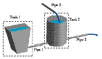
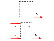
| | 1. Draw a situation sketch. Create a sketch of the system to be investigated, and its environment. The sketch should be half realistic, and can contain information about the sizing of the system and its parts (Figure 1). 2. Choose systems or elements. Choose one or several systems, subsystems, or elements. A system is either an identifiable body or a region of space (icontrol volume). Here we choose two control volumes containing the tanks in the Figure. Generally, there is more than one way of choosing elements. 3. Choose quantities to be accounted for. In hydraulics, the quantities to be accounted for are amounts of fluid (volumes). 4. Cut systems or elements out of environment and identify processes. Draw abstract representations of the systems chosen (such as the dashed rectangles in Figure 2). Identify all the flows since these represent the processes (to find them, ask why there are processes and “walk around” the system to find inputs and outputs). Draw an arrow for each flow with respect to its system. Label the arrows. Enter the stored quantities (Figure 2). (Step 4 is called creating free body diagrams.) 5. Formulate laws of balance. For each of the subsystems and for each of the stored quantities, a law of balance is formulated (Figure 3, normally in dynamical or instantaneous form). A law of balance relates all processes to how fast the system content changes:  1.6 1.6
6. Formulate interaction rule. In our example, there is a single interaction: The flow out of Tank 1 equals the flow entering Tank 2 through the pipe joining them (Figure 3):  1.8 1.8
| | | |
 1.6
1.6

