| 4 | Charging and discharging a single capacitor |
|
|
| Main | A capacitor is charged and then discharged through resistors. The voltage across the capacitor is measured as a function of time. The voltmeter adds to the dynamics of the circuit. More…
|
Photographs | |
| Movies |
|
| Data files | |
| Models | |
| |
| Sections | |
|
| |
| Description | DESCRIPTION OF EXPERIMENT |
| Experiment | A capacitor is charged and then discharged through resistors. The voltage across the capacitor is measured as a function of time. The voltmeter adds to the dynamics of the circuit. First, both branches of the circuit are open. At t = 10 s, the power supply is connected so as to close the first branch—the capacitor is charges until t = 80 s. Then, the first branch is opened again—both branches are open until t = 400s when the second branch is closed to discharge the capacitor. Data is taken with the help of a differential voltage probe. [Note that the closing/opening of the branches is performed manually by inserting/ removing circuit elements. See the photos.]
|
| Dimensions | Capacitance of capacitor: 470 µF (nominal) Resistance of resistor in charging branch: 9.88 kOhm Resistances of resistor 1 and 2 in discharging branch: 9.88 kOhm and 97.9 kOhm Resistance of differential voltage probe: 8–12 MOhm |
| |
| Sections | |
|
| |
| Assignment | A POSSIBLE PATH THROUGH THE INVESTIGATION… |
| Basics | Investigate the experiment, make sure you understand the setup of the system and the initial conditions. Draw a circuit diagram representing the system. Plot the data (Charge_Discharge_Cap.xls) to get a feeling for the dynamical process. Estimate time constants of the processes. Create a word model for the system and its processes. Create a formal dynamical model (consult with the models of the previous three Investigations), import data, simulate the model and determine the parameters of the model by comparing simulation and experimental data. What is the role of the differential voltage probe?
|
Particulars | Note that the measured voltage does not seem to go back to exactly 0 V. How do you deal with this? Change parameters (including initial values) and perform simulations to learn about the behavior of this system. In particular, investigate the influence of the voltage probe. |
| |
| Sections | |
|
| |
| Model | MODEL EQUATIONS AND MORE… |
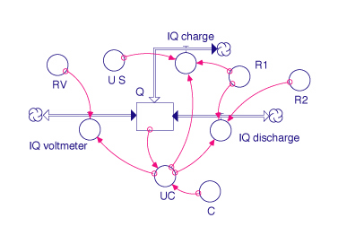
| | Laws of balance dQ(t)/dt = IQ_charge - IQ_voltmeter - IQ_discharge
INIT Q = C*UC_init
Flows IQ_charge = IF (TIME < 10) THEN 0 ELSE IF (TIME < 80) THEN -(UC-U_S)/R1 ELSE 0
IQ_discharge = IF (TIME < 400) THEN 0 ELSE UC/(R1+R2)
IQ_voltmeter = UC/RV
Relations UC = Q/C
Parameters C = 470e-6
R1 = 9.88e3
R2 = 97.9e3
RV = 1e6
U_S = IF (TIME < 10) THEN 0 ELSE IF (TIME < 80) THEN 3.00 ELSE 0
UC_init = 0
|
| |
| Sections | |
|
| |
| Questions | SOME SIMPLE QUESTIONS… |
| 1 | What kind of function of time do you expect for the voltage across the capacitor during discharging? (See the graph of experimental Data) How do you verify that your idea applies to this case? |
2 | What should be the function of time of U_C during charging? |
3 | What are the time constants of charging and of discharging? |
4 | During which phase of the experiment do you see most clearly that the voltmeter seems to have a noticeable influence upon the behavior of the circuit? (See the graph of experimental Data) How can you model this influence? How do you determine parameters of the voltage probe? (Which ones?) |
5 | Does the presence of the voltmeter change anything about the data taken for charging of the capacitor? In particular, is the maximum voltage reached influenced by the voltmeter? |
|
| |
| Sections | |
|
| |