| 11 | Electric model of a windkessel |
|
|
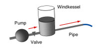
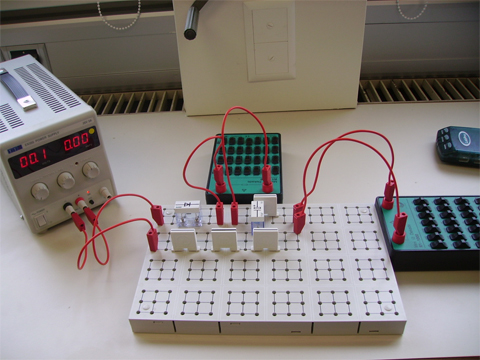
| Main | An electric circuit is built consisting of a capacitor, two resistors, and a diode. The circuit models a (hydraulic) windkessel pump, where the pump is represented by a power supply (voltage source) whose voltage is changed rythmically. The voltage across the capacitor is measured. More…
|
Photographs | |
| Movies |
|
| Data files | |
| Models | |
| |
| Sections | |
|
| |
| Description | DESCRIPTION OF EXPERIMENT |
| Experiment | An electric circuit is built consisting of a capacitor, two resistors, and a diode. The circuit models a (hydraulic) windkessel pump, where the pump is represented by a power supply (voltage source) whose voltage is changed rythmically. The voltage across the capacitor is measured. The voltage of the power supply is measured as well. Its values (as a function of time) can be used as input to a dynamical model — it represents the pump that drives the dynamics of the windkessel system. There is a diode simulating the valve between the pump and the windkessel. The valve is there to prevent backflow. It opens only when the pressure at the outlet of the pump is higher than in the windkessel.
|
| Dimensions | Diode: IN4007 Capacitor: 470 µF R1: 1,000 Ohm R2: 10,000 Ohm |
| |
| Sections | |
|
| |
| Assignment | A POSSIBLE PATH THROUGH THE INVESTIGATION… |
| Basics | Investigate the experiment, make sure you understand the setup of the system and the initial conditions. Draw a circuit diagram representing the system. Plot the data (Electric_Windkessel.xls) to get a feeling for the dynamical process. Estimate time constants of the processes. Create a word model for the system and its processes. Create a formal dynamical model (consult with the models of previous Investigations and the examples of hydraulic windkessel models in the Activities section of Chapter 1), import data, simulate the model and determine the parameters of the model by comparing simulation and experimental data. Why isn't there a single loop in the circuit? (Why is the second resistor in parallel and not in series with the capacitor?) What is the role of the differential diode?
|
Particulars | What is the simplest model of a diode if you assume that it lets charge pass if the voltage across it and the series resistor is larger than a certain fixed value? (Which is to say that charge does not pass at all if the voltage is lower.) Change parameters (including initial values) and perform simulations to learn about the behavior of this system. Change the input voltage of the drive (amplitude and frequency). |
| |
| Sections | |
|
| |
| Model | MODEL EQUATIONS AND MORE… |
| |
|
| |
| Sections | |
|
| |
| Questions | SOME SIMPLE QUESTIONS… |
| | |
|
| |
| Sections | |
|
| |