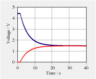
Two capacitors and a resistor are made into a circuit containing a switch. One of the capacitors is charged, then the switch is closed. Voltages across the capacitors are measured as functions of time (see Graph). The capacitance of the larger capacitor is equal to 60 µF. The resistance of the resistor and the other capacitance are to be determined.
a. Compare the process described here with the equilibration of levels of liquid in two communi- cating tanks (see Chapter 1). Use analogical reasoning to explain how the electric system works. Which electrical quantities correspond to which hydraulic ones? b. Which of the two measured functions corresponds to the capacitor having the larger capacitance? Why? c. Use the value of the final voltage reached by both capacitors to calculate the value of the unknown capacitance. Which concepts are used to perform this calculation? What do you assume about the capacitances? d. What is the meaning of the difference of the voltages U_C1 – U_C2? Why should it be equal to the voltage across the resistor? e. How are the rates of change of voltages in the diagram used to find the flow of electric charge from one capacitor to the other one? How can the result be used to find the characteristic of the resistor? f. Determine the time constant of this circuit. (Note, the time constant is found from the change of the functions relative to the final common level.) | | g. Calculate the total capacitance of the circuit. (It is found from calculating the inverse of the sum of the inverse capacitances. Why is this so?) h. Use the total capacitance to find the value of the resistance of the resistor in the circuit.
Click to obtain pdf for printing
|