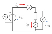
a. Assume the measuring devices to be ideal. We measure U_S = 10.13 V and I_Q = 100.4 mA. What is the resistance of the resistor taking these measurements?
b. Volt meters and ammeters are not ideal. They can be modeled as devices letting electric currents pass while having certain values of internal resistance. In a first step toward a more accurate determination of the resistance of the resistor, assume the voltmeter on the right to be ideal. It reads a value of U_V2 = 10.01 V. What is the internal resistance of the ammeters and the resistance of the resistor?
c. Now create a model of the complete circuit, i.e., formulate all relevant relations for the circuit and the elements found in it.
d. Use the complete model to determine the internal resistances of the ammeters and the voltmeters, and the resistance of the resistor. (Measurements: U_S = 10.13 V, U_V2 = 10.01 V, I_Q = 100.4 mA, I_QR = 99.9 mA.)