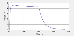
A single capacitor is charged and discharged. Charging takes place btween t = 10 s and 80 s in a circuit having a battery and a resistor. At t = 80 s, the charging circuit is opened. At t = 400 s, a second connected circuit with the capacitor and two resistors in series is closed, and discharging sets in. During the entire process of charging and discharging, a voltage probe is conneted to the capacitor to measure U_C(t). The voltage probe has a high internal resistance of some MOhm. Data of the voltage across the capacitor is shown in the diagram below.
a. Draw a circuit diagram that corresponds to this experiment, and describe the experiment in you own words. b. The resistance of the resistor in the charging circuit is 9.88 kOhm. Use the enlarged section of the graph (Click for pdf and print) to determine the time constant of charging. Do this directly from the graph, and again by creating a logarithmic representation of data. c. Use the determination of the time constant to find the capacitance of the capacitor. d. From t = 80 s to t = 400 s, the measured voltage decreases slowly. Use this to calculate the resistance of the voltage probe. Taking the effect of the voltage probe into account, do you have to change the determination of the capacitance of the capacitor (Problem c)? e. What is the voltage set up by the battery? Why is it higher than the 4.61 V reached by the capacitor shortly before t = 80 s? | | f. Use data on discharging to calculate the total resistance of the resistors in the circuit used for discharging. What is the role of the volmeter during this phase? g. Sketch the diagram of a system dynamics model that can be used to represent the system and its processes discussed here. |