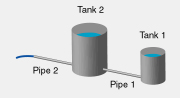
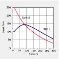
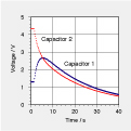
Consider two communicating tanks (one smaller, one larger) where the larger one has an additional outflow. In the accompanying graph (left), level data for the two tanks is reported as functions of time. The system is to be modeled electrically. Data for an equivalent electric system is shown in the graph on the right. (Here, the capacitances are 30 µF and 60 µF, respectively.)
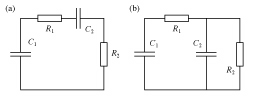
a. On the right, two possible versions of electric circuits are shown. Explain why the second one (b) represents the dual tank system, whereas the first one (a) does not. b. Introduce currents in circuit (b) and write the laws of balance of electric charge for the two capacitors. c. Use the graph of voltage data to determine the rates of change of voltages for the capacitors right at the moment when the circuit is closed. Use this to calculate the electric currents in the two branches of the circuit. d. Calculate the resistances of the resistors in the circuit. e. How much charge has been transported from capacitor to capacitor until the voltages have become equal (at about 5 s)? In which direction has charge been flowing? f. Why are the voltages of the capacitors equal (at 5 s) exactly as the voltage of the first capacitor reaches its maximum? g. Compare the experimental results for the levels in the two tanks (graph on the left) and the voltages of the capacitors (graph on the | | right). They appear to be quite similar at first sight. However, the shape of the functions is decidedly different. (In a simple model, voltages are exponential functions, whereas levels are not.) Why is this so? |