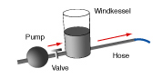
A hydraulic windkessel system having an ideal pump is to be modeled and designed electrically. The first diagram shows the voltage across the ideal power supply and across the capacitor. Assume resistances and capacitances to be constant. The resistance of the resistor corresponding to the long pipe of the windkessel is 10 ohm.
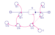
a. Sketch an electric circuit diagram that corresponds to the windkessel system. Label and explain your diagram. b. Shortly after turning on the power supply, the voltage across the capacitor reaches a constant value (roughly between 75 s and 80 s). Why is that? Why does the capacitor voltage never reach the 10 V of the power supply? Use this observation and your explanation to determine the ratio of the two resistances in the circuit. c. Use the system behavior to show that the capacitance of the capacitor is 1.0 F. d. How is the energy current from the power supply to the capacitor determined? Can you use this energy current to calculate the energy of the capacitor? If so, how? e. The tank in the hydraulic system is to be modeled by two identical capacitors. There is a resistor between the capacitors. Complete the SD model diagram to reflect this situation. What is the capacitance of one of the capacitors? f. Explain how the electric current between the two capacitors in your SD model is calculated. | | g. Use the data of the second diagram to sketch as carefully as possible the current between the capacitors for one cycle (between 60 s and 90 s). The resistance of the resistor is 2.0 ohm. |