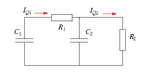
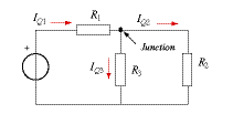
We need to find the objects that store electric charge and then identify all the transports of charge with respect to them. This leads to expressions for the balance of charge for every such object. In a circuit having two capacitors as in Figure 1, there are two storage elements. There is a single current with respect to the first. On the other hand, there are two currents leading into or out of the second capacitor. One of the currents is equal to the one leading into or out of the first capacitor. In system dynamics diagrams, laws of balance in their instantaneous forms can be represented graphically by combinations of storage and flow symbols (Figure 2). For each of the subsystems and for each of the stored quantities, a law of balance is formulated (normally in dynamical or instantaneous form). A law of balance relates all processes to how fast the system content changes: This is the form of the laws of balance applicable to the system of Figure 1. Many applications in electricity use circuits that do not have real storage elements leading to dynamical processes. Figure 3 shows the diagram of a circuit that leads to steady-state processes. Charge is not stored anywhere. However, there still is an element for which a law of balance of charge has to be expressed. This is the junction in Figure 3 for which we write the junction-rule (Kirchhoff’s first law): |

Figure 1

Figure 2

Figure 3 |


