5. Constitutive Laws: Capacitors, Batteries, and Flows | | 
| | Constitutive laws, or special laws, are relations that depend upon the types of elements used in a system, and upon circumstances. In contrast to the laws of balance, the loop rule, or the expression for power, they are not general. They describe the peculiarities of processes and objects. There are constitutive laws covering all different types of processes. In particular, there is at least one special law for each particular potential difference occurring in a system.
Storage of charge in capacitors Storage elements are responsible for the dynamics found in systems. They work by providing a relation between amounts of stored charge and the voltage set up across them. Storage elements are capacitors. Capacitive characteristic. There is a relation between the charge stored and the associated voltage (which we call a capacitive voltage U_C). The relation is called a capacitive characteristic (Figure 1, top). Another way of representing the relation is by drawing a fluid image (Figure 1, bottom). In general, the characteristic is nonlinear. A linear characteristic is related to a constant capacitance. Elastance and capacitance. The characteristic relation can be expressed mathematically if we introduce the elastance alpha_Q, i.e., the factor which tells us how easy it is to increase the voltage with a given amount of charge: alpha_Q is equal to the slope of a tangent to the characteristic curve (Figure 1). This means that the elastance measures the “stiffness” of the storage system. The unit of elastance is V/C. Alternatively, we can introduce the electric capacitance C_Q or simply C (units C/V = F (Farad)) which is defined as the inverse of the elastance (C = 1/alpha_Q):
Energy stored in capacitors. The fluid image of a capacitor in Figure 1 lets us calculate the energy stored with charge in a capacitor. The charge stored is represented as the content of the imaginary tank. The equation for the energy associated with this storage is the same as the one for the energy necessary to stack a real fluid in a real tank here on Earth. For a capacitor having constant capacitance, stacking charge in the tank is like placing it all at half the total height. Therefore: |
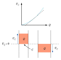
Figure 1
|
Batteries Process diagram. Batteries make electric charge flow, and they increase the electric potential of charge. This simple fact is best represented in a process diagram of the type shown in Figure 2. Process diagrams represent a system (or an element of a system) and show what happens with the basic quantities (here: current of charge, voltage, and energy related quantities) used to describe a electric process. In a real battery, a part of the energy released by the chemical reaction is used to produce heat (as long as there is an electric current in the circuit with the battery). This reduces the voltage set up by the chemical reactions. Characteristics of batteries. Characteristic diagrams of batteries are simple linear curves: The voltage across the terminals decreases with increasing electric current (see Figure 3). The formal description of the characteristic is U_B is the voltage measured across the terminals, U_0 is the maximum possible voltage (the open circuit voltage), I_Q is the current through the battery, and R_i is the internal resistance of the battery (Figure 4). Maximum power of a battery. Figure 5 shows again the characteristic diagram of a standard battery. The voltage across the terminals decreases if the current increases. The useful power of the battery, i.e., the rate at which energy is supplied to the electric process driven by the battery, is determined by the product of the voltage across the terminals and the current through the battery (Figure 4). The maximum is achieved when the resistance of the load resistor is made equal to the internal resistance of the battery. |
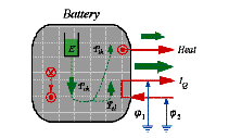
Figure 2
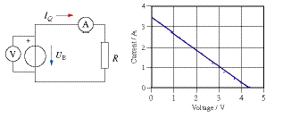
Figure 3
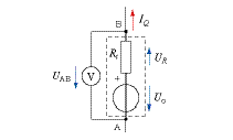
Figure 4
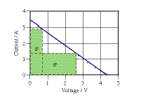
Figure 5 |
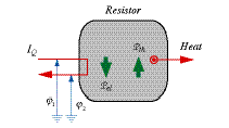
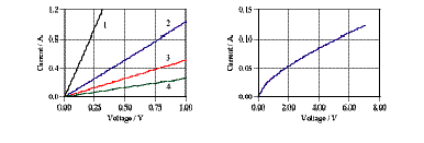
Resistive transport of charge When electric charge flows through what we normally call resistors or conductors, heat is produced. This is the main characteristic of the type of transport we are considering here. Obviously, there are transports that are not resistive such as the main phenomenon in a battery or the part of the flow of electricity through a motor that drives the engine. Process diagram. Charge flows through a resistor (or a conductor) from higher to lower electric potentials which means that energy is released as a result of this transport. The energy released is used to produce heat (Figure 6). Ohmic transport of charge. The transport of charge in metallic conductors satisfies a simple relation. For small voltages or electric currents, the current is proportional to the potential difference across the conductor. Therefore, the characteristic relation is linear (Figure 7, left). In this case, we can write the flow law with the help of a conductance G (units A/V = 1/Ohm) or its inverse, the resistance R (V/A = Ohm): Resistance for ohmic transport in conductors having constant cross section: l and A are the length and cross section of the conductor, respectively, and rho_el is the resistivity of the material. The inverse of the resistivity is called the electrical conductivity: sigma = 1/rel (unit: S/m, S: siemens). Ohm's law. Generalization of this expression suggests that dphi_el/dx is the gradient of phi_el, and j_Q is the current density. Temperature dependence of sigma may lead to nonlinear characteristic curves as for the filament of a light bulb (Figure 7, right). The temperature dependence of resistivity is commonly approximated by a linear (or if necessary a quadratic) function of temperature. The coefficient a multiplying the linear term is called the (linear) temperature coefficient of resistivity: 
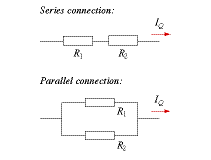
Series and parallel connections of ohmic resistors. If ohmic resistors having constant resistances are combined in circuits (Figure 8), series (top) and parallel (bottom) combinations can be replaced by equivalent resistors. For series connections: If several resistors are connected in parallel (Fig. 8, bottom), the inverse of the equivalent resistance equals the sum of all inverse values of the individual resistances:
Power of an ohmic resistor. The electric power of a resistor is calculated from the standard expression and can be expressed either with voltage or with the current: Transport of charge in diodes. An example of a diode characteristic is seen in Figure 2. The current can be approximated by an exponential function of the voltage U_D across the diode: I_0 is called the saturation current, n is an emission coefficient with a value of somewhere between 1 and 2 (depending on the material and the fabrication of the diode). e is the elementary charge (1.60·10^–19 C) and k = 1.38·10^–23 J/K is Boltzmann’s constant. T measures the absolute temperature in Kelvin (Chapter 3). | | | |


