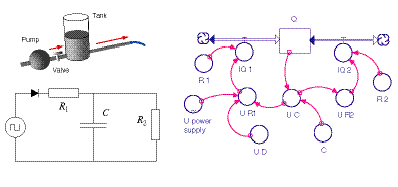
Dynamical models Dynamical models combine laws of balance with the appropriate constitutive laws. They are created by a combination of steps described above in Section 2 (Systems analysis I: Laws of balance) and Section 3 (Systems analysis II: Potential differences), with the particular laws for special processes found in Section 5 (Constitutive laws). Expressions for energy relations (Section 4) can be added to the dynamical models. If the model describes a dynamical situation, it may be expressed with the help of a system dynamics tool. A system dynamics diagram represents the necessary laws of balance and constitutive laws. The example of Figure 1 is for an electric circuit that is equivalent to a simple hydraulic windkessel model. Mathematically speaking, the completed model is a set of equations that have to be solved during simulation. The equations comprise a single differential equation for the law of balance of charge of the capacitor. Then there are equations for the relations between voltages in the two branches of the circuit. Finally, there are expressions for the capacitance of the voltage of the capacitor, and for the electric currents. Analytical solutions Systems made up of capacitors and resistors show simple behavior. Complex behavior is the result of the interaction of several simple elements. For the simplest systems—those having constant values of capacitance and resistance—analytic solutions of the model equations can be obtained. In the case of discharging a constant capacitance capacitor through an ohmic resistor we get (Figure 2): 
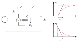
If an empty capacitor is charged, the solution of the model is (Figure 1, righ top): These results also hold for the charge stored in the capacitor. We simply multiply the equations by the capacitance to obtain the new results.
Time constants The behavior (capacitive voltage as a function of time) for the simple cases of charging and discharging of a capacitor is shown in the accompanying graphs of Figure 3. The solutions of the model are exponential functions. A measure of how fast (or slow) the process is, is the time it would take for the capacitor to charge or discharge were the voltage to continue to change at the initial rate. This time is called the capacitive time constant tau_C of the system. In one time constant, the capacitive voltage in the system shown on the left in Figure 1 drops to 1/e = 0.37 times the initial level. The analytic solutions demonstrate that |

Figure 1

Figure 2

Figure 3 |


