| 4 | Two communicating water tanks having an additional outflow |
|
|
| Main | Two different cylindrical tanks filled to different levels are connected by a pipe. One of the tanks has an additional outlet. As water flows, data of levels in the two tanks is collected. More…
|
| Photographs | Six photos of the process, spaced by 20 seconds: |
| Movies | |
| Data files | Data from a different experiment than the one shown in the photographs: |
| Models | |
| |
| Sections | |
| |
| Description | DESCRIPTION OF EXPERIMENT |
| Experiment | Two different cylindrical tanks filled to different levels are connected by a pipe. One of the tanks has an additional outlet. As water flows, data of levels in the two tanks is collected. The water levels are measured from above using ultrasonics for one of the tanks, a floater for the other. [Note that in the photograph, the end of the outlet pipe is lower than the bottom of the tank. The data reported here was taken for a different case with the outlet perfectly horizontal at a level equal to the bottom of the tank.]
|
Dimensions | Tank 1: Inner radius: 49.5 mm Tank 2: Inner radius: 74.5 mm Pipe 1: Inner radius: 3.0 mm, length: 500 mm Pipe 2: Inner radius: 3.0 mm, length: 250 mm |
| |
| Sections | |
| |
| Assignment | A POSSIBLE PATH THROUGH THE INVESTIGATION… |
| Basics | Investigate the experiment, make sure you understand the setup of the system and the initial conditions. Plot the data to get a feeling for the dynamical process. Estimate time constants of the processes. Create a word model for the system and its processes. Create a formal dynamical model (start with the model of communicating tanks: Investigation 2), import data, simulate the model and determine the parameters of the model by comparing simulation and experimental data.
|
Particulars | Change parameters (including initial values) and perform simulations to learn about the behavior of this system. Change the model to include an outlet leading to a lower point than the table top. |
| |
| Sections | |
| |
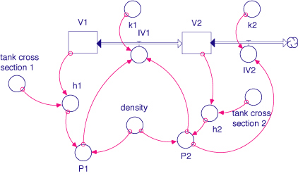
| Model | MODEL EQUATIONS AND MORE… |
| | Laws of balance dV1(t) / dt = - IV1
INIT V1 = h1_0*tank_cross_section_1
dV2(t) / dt = IV1 - IV2
INIT V2 = h2_0*tank_cross_section_2
Flows IV1 = IF ((P1-P2) > 0) THEN SQRT((P1-P2)/k1) ELSE -SQRT(-(P1-P2)/k1)
IV2 = SQRT(P2/k2)
Relations h1 = V1/tank_cross_section_1
h2 = V2/tank_cross_section_2
P1 = 9.81*density*h1
P2 = 9.81*density*h2
tank_cross_section_1 = PI*(0.099/2)^2
tank_cross_section_2 = PI*(0.149/2)^2
Parameters h1_0 = 0.102
h2_0 = 0.248
density = 1000
k1 = 2.5e13
k2 = 0.48e13
length_1 = 0.500
length_2 = 0.250
pipe_radius = 0.003
|
| |
| Sections | |
| |
| Questions | SOME SIMPLE QUESTIONS… |
| 1 | Why does the water level in Tank 1 first rise and then fall? (See the blue curve of the graph of experimental Data) |
2 | Why is the water level in Tank 1 higher than in Tank 2 after it starts falling? |
3 | Why is the maximum level in Tank 1 right at the point where the two water levels have reached the same value? |
4 | Why is (the magnitude of) the rate of change of level higher for Tank 2 than for Tank 1 right at the beginning of the process? |
5 | What would be the levels as functions of time if the level of water were higher in Tank 1 than in Tank 2 at the beginning? Are there different possibilities depending upon the particular initial values? |
6 | How is the flow through the pipe connecting the two tanks calculated? |
7 | The flow of water through the pipes is taken to be turbulent in this model. Is it possible for the flow to be laminar at least for part of the time? |
8 | Assume that during the experiment the end of the outlet hose was lower than the table on which the two tanks are placed. How would the process be changed? How is this change Included in the dynamical model? |
9 | How would the model equations have to be changed if vegetable oil were used in place of water? |
| |
| Sections | |
| |