
CHAPTER 1
|
|
ACTIVITIES > PROBLEMS > PROBLEM 151 | 2 | 3 | 4 | 5 | 6 | 7 | 8 | 9 | 10 | 11| 12 | 13 | 14 | 15 | 16
|
15 |
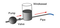
A model of a windkessel pump |
|||
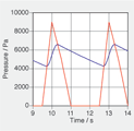
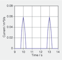
The windkessel pump was invented for fire fighting purposes. The hand operated pumps worked intermittently. By placing a storage vessel (windkessel) between the pump and the hose, the flow could be made much smoother. (Windkessel functions can be found in different examples in nature and engineering. Example: Heart and aorta.)Data is given in graphical form for a particular example. The pump increases the pressure difference at fixed intervalls (graph on the left, red curve). The resulting pressure of the liquid at the bottom of the tank (blue curve) is smoother and at an intermediate level.The flow leaving the pump (when the pressure of the pump is greater than the fluid pressure in the tank) is strongly pulsed (like the pressure difference established by the pump).
|
|
|||